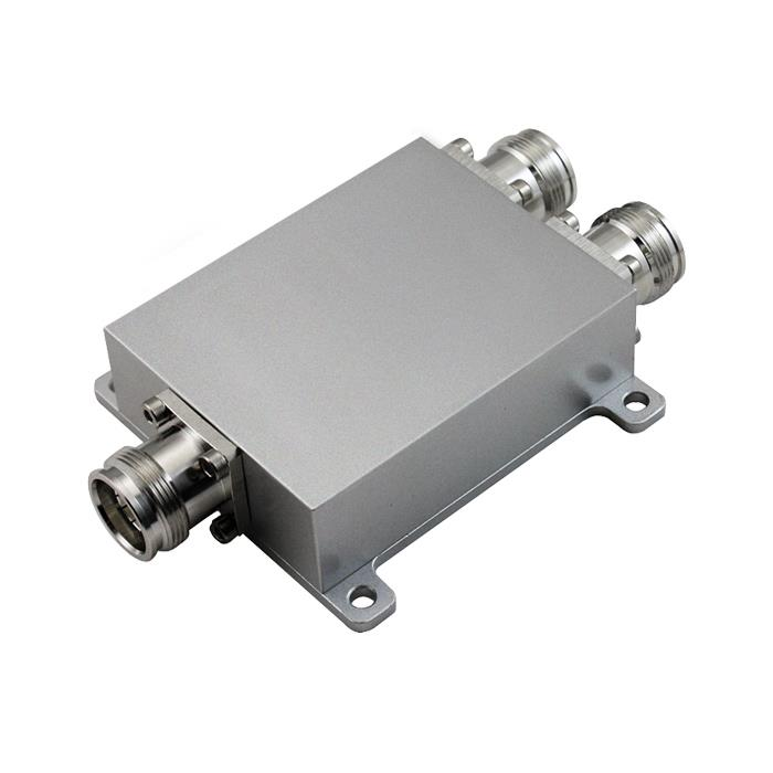
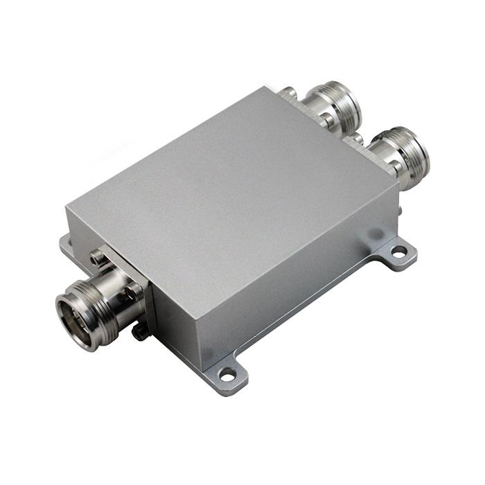
Power splitter technical indicators introduction

In general, selecting a power splitter or combiner is a matter of comparing key performance parameters, including insertion loss, isolation between ports, amplitude proximity of the split signals (output amplitude imbalance), and signal phase proximity of the split signals (output amplitude imbalance). phase imbalance). In addition, the power rating is often critical and is defined in terms of maximum input power (assuming impedance matching) and maximum internal load dissipation (power rating of the internal termination). Another key parameter is return loss, or VSWR, which indicates how well the component impedance matches the characteristic impedance of the intended application.
The power splitter will cause the output signal to have a phase difference. For example, a 0° power splitter splits an input signal into two or more outputs of the same magnitude and phase. The phase difference between the output signals of the 90° hybrid splitter is 90°. For a 180° hybrid splitter, an input signal can be split into two output signals with the same amplitude and phase when the input is applied to the input port. But when the input signal is added to a different input port, the obtained output signal has the same amplitude, but a phase difference of 180°.
The technical indicators of a power splitter include frequency range, withstand power, distribution loss from the main circuit to branch, insertion loss between input and output, isolation between branch ports, voltage standing wave ratio of each port, etc.

Power splitter technical indicators:
The technical indicators of a power splitter include frequency range, withstand power, distribution loss from the main circuit to branch, insertion loss between input and output, isolation between branch ports, voltage standing wave ratio of each port, etc.
1. Frequency range. This is the working premise of various RF/microwave circuits, and the design structure of the power splitter is closely related to the operating frequency. The operating frequency of the distributor must first be clarified before the following design can be carried out
2. Withstand power. In a large power splitter/synthesizer, the maximum power that the circuit elements can withstand is the core indicator, which determines what form of transmission line can be used to achieve the design task. Generally, the order of transmission line power from small to large is microstrip line, stripline, coaxial line, air stripline, and air coaxial line. Which line to use should be selected according to the design task.
3. Distribution loss. The distribution loss from the main circuit to the branch circuit is essentially related to the power distribution ratio of the power splitter. For example, the distribution loss of the two-half power splitter is 3dB, and the distribution loss of the four-half power splitter is 6 dB.
4. Insertion loss. The insertion loss between the input and output is due to factors such as the imperfect medium or conductor of the transmission line (such as a microstrip line), and the loss caused by the standing wave ratio at the input end is considered.
5. Isolation. The isolation between tributary ports is another important indicator of the power splitter. If the input power from each branch port can only be output from the main circuit port, and should not be output from other branches, this requires sufficient isolation between the branches.
6. Standing wave ratio. The smaller the VSWR of each port, the better
The above is an introduction to the technical indicators of the power splitter. As a power splitter manufacturer, CenRF specializes in R&D and the production of power splitters. If you are interested in a power splitter, please pay attention to our website.
Related Recommendation:
What are the advantages of repeaters?
Some tips when installing and setting up repeaters


